In the final year of my degree course we had to design and implement a project entirely of our own choosing – some made iOS apps, some made travel/mapping aids, all manner of things. I was personally quite stuck on what I wanted to do – it’s difficult to decide what you want the biggest project you’ve built thus far to be, especially given the choice of potentially doing something easier and getting it done sooner. I began looking through the personal pages of every lecturer who was available as a project overseer, and came across the suggestion of trying to solve a jigsaw puzzle. At first I skipped over it because when I thought about how I’d implement it, my brain returned a big fat null.
Ultimately, that’s the very reason I chose it. “No point in half measures,” I thought, so I jumped in to the deep end of a project with no clue how I was going to make it happen.
I had a few months before I actually started work properly, so I did a modicum of research so I at least knew the area. There’s a lot of systems in the jigsaw puzzle area, but the varying definitions of a puzzle quickly became a problem. I see a jigsaw as a series of pieces with interlocking segments of some form, whereas some seem to class an image just cut in to perfect squares as a jigsaw. Obviously that’s completely different to what I wanted to do – take a physical puzzle, digitize it, and run that through some program which would give me at least a partial solution. Attempts have been made at those refined goals dating back to the 60s, and these research papers proved invaluable
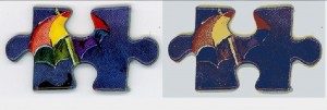
The first stage of this process is acquiring the physical pieces in some manner. Others previously had photographed each piece individually with controlled lighting, photocopied and then scanned the pieces, and even hand-traced the piece outlines. I made some attempts at photography, but the noise generated by the consumer- and mid-range cameras available (and, in particular, their use of jpeg) made them hard to work with at the pixel level. Instead I fired up my aging scanner, arranged the puzzle pieces face down and took a few scans at various DPI’s. The ideal I arrived at was 300 DPI, and the images were clear and well defined, although problems were created, which we’ll discuss in a moment.
With a high quality image of the puzzle, I began looking at some processing removing the pieces from the background. I tried a selection of edge detection and thresholding algorithms via the Python library Gamera, having some knowledge of their use from a previous University class on Graphics, but none of them gave me reliably good results in different scenarios. In parallel to this I was developing the next stage which walks the pixels of the processed image and gets a pixel-wise representation of the outline of each piece, so I was able to test the Gamera images directly in this code, and the results were nasty. Pieces where the face image contained the background colour, and where that section bridged a join between two pieces would have large chunks cut out of their centers because the outline was basically erased by the thresholding algorithms. This prompted the decision to scan the rear of the pieces so I could avoid this problem, which meant I would be unable to do any processing based on the piece images.
With this method adjustment, I was able to choose an algorithm, but a further problem stopped me before I’d even begun implementing it. Since the scanner contains a bright light, shadows were cast at the edges of the puzzle pieces which the thresholding failed to distinguish from the pieces themselves. Some effort was made to resolve this problem, but I soon began looking at other methods. In the end, I implemented a median cut posterization to ~4 colours which seperated the white background, blue pieces and dark grey shadows well, although this did require a manual step where the user selects which colours to remove.

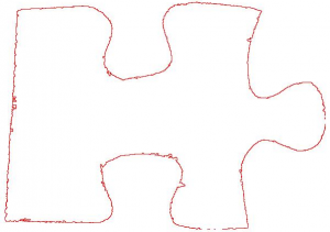
Extracting the piece outline is simple in theory, but the implementation took a lot of debugging. This section of the program was based on Potrace, which aims to vectorise low quality bitmap images by tracing the shape edges and applying a smoothing algorithm to remove the bitmap imperfections. My edge tracing implementation was based exclusively on the Potrace paper, and developed with small 20×20 images until it was stable, as below.
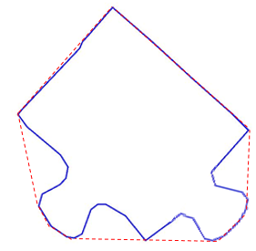
The next smoothing stage is performed by a simple Ramer-Douglas-Peucker algorithm, which takes the first and last point in a list of points describing a line, and finds the point within the list that is furthest from the line segment of the starting points. If this distance is greater than the given threshold value the algorithm recursively calls itself with this furthest point and both the start and end points, effectively subdividing the list of points. This recursion continues until the furthest value from a subset of points is less than the threshold, which means it can be resolved to a single line segment. Once all the recursion bubbles up, the list of points is massively reduced in length, and lacking most of the jagged edges.

However, as can be seen, some problems remain. Ramer-Douglas-Peucker will smooth the lines, but if the visual error is larger than the threshold value it will get left behind! A simple second step was devised which corrected many of the problems. In essence, it searched for a trio of consecutive vertices which represented a large angle change, and then scanned a square area of n*n (based on line segment length and other global conditions) immediately after the mid-point of the three being tested, in the direction of the first line segment. Any points found within the square are added to a list along with their Euclidean distance from the mid-point, with the lowest-distance point finally being chosen to connect to the mid-point. All data between the mid-point and the new end point is removed.

Now there is a reasonable representation of the pieces’ shape we can start thinking about comparing pieces. Obviously we want to compare each of the four edges, but currently we just have one big list of points for each puzzle piece. We need to find the corners.
An initial experiment was made using convex hulls, thinking they would expose the corner points well, and in some cases they did…

…in many cases however, they didnt…
The convex hulls didn’t last long as an experiment. The final solution relies on the puzzle pieces (and the internal representation) having sharp square corners, since it basically iterates over the points list searching for a pair of line segment within a threshold of 90 degrees. Since many points along the intersecting edges of a puzzle piece can approximate 90 degrees, a second verification step was implemented which tests each point by extending the line segments on either side until they reach the edges of the pieces bounding box to form a large triangle. If the center point of the pieces bounding box is within the triangle created, the point is kept, otherwise it’s discarded.

Across the three puzzles I tested with, this simple pair of methods correctly classified 77% of corners. A manual system was implemented to correct the corner detector after it’s run.
Now the real meat of the problem can begin: Solving! My implementation is based to that of Wolfson et al in “Solving jigsaw puzzles by computer”, with the aim to produce a rotation and scale invariant “signature” for a series of line segments, based on the change of angle between each of them. The final output is something like below…

One small inconvenience of this approach is that while it is mostly invariant, the direction of movement through the point list while generating it does matter. To compare two edges of different pieces one piece must have its signature generated in reverse. In practice, this means every piece must have forward and reverse signatures for every side.
The system was not successful in solving puzzles, but it came very close. Time lost to early problems with acquiring the puzzle pieces and noise was difficult to recover, and trying to balance the level of detail required to successfully solve against the amount of polygonal smoothing that was required proved very difficult. In the end I received a mark of 72% in the project. A video of the final version running can be found below, as well as full output images from each stage of it’s operation.
For anyone interested, you can download the source as well as three of the images I used to develop the system. You’ll need to get the Java Advanced Image IO library too, a link’s included in a txt file with the source.


